Extended Flange Plate Settings
- General Overview
- Tips and Tricks
- Related Tools
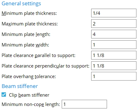
General settings
Minimum plate thickness: The minimum thickness of the extended flange plate.
Maximum plate thickness: The maximum thickness of the extended flange plate.
Minimum plate length: The minimum length of the extended flange plate measured parallel to the beam's work line. This width applies to both the NS and FS extended flange plates.
Minimum plate width: The minimum width of the extended flange plate measured perpendicular to the beam's work line. This length applies to both extended flange plates.
Plate clearance parallel to support: The distance the extended flange plates extend beyond the base/cap plate edges, measured parallel to the beam's work line.
Plate clearance perpendicular to support: The distance the extended flange plates extend beyond the base/cap plate edge, measured perpendicular to the beam’s work line.
Plate overhang tolerance: The distance the edge of the base/cap plate is allowed to extend beyond the beam flange edge before connection design attempts to design extended flange plates and stiffeners.
Beam stiffener
If this box is checked (
), connection design is permitted to create beam stiffener plates that taper to fit to the extended flange plates. These flange plates extend the effective flange width of the beam.
If the box is not checked (
), rectangular, non-tapered beam stiffeners will be designed.
Minimum non-cope length: The minimum distance from the outside corner of the stiffener plate that is nearest to the extended flange plate to the corner where the stiffener plate begins to taper.


|
|
OK (or the Enter key) closes this screen and applies the settings.
Cancel (or the Esc key) closes this screen without saving any changes.
Reset undoes all changes made to this screen since you first opened it. The screen remains open.
-
Extended flange plates and stiffeners can be designed for a column cap plate to a beam flange or a column base plate to a beam flange.
- Use extended stiffeners (user base/cap plate)
- Use extended stiffeners (auto base/cap plate)
- Top / Bottom Extension Plates (connection design locks)
- Beam flange extension plates with tapered stiffeners (Connection Guide)

